3D Printing Around Poor VRM Cooling
Not too long ago, my personal desktop ran an AMD FX-8350 processor. This processor was from the early 2010s, and being an AMD processor, had extremely poor energy efficiency. The benefit: in the cold months of upstate New York, my computer was a fantastic radiator that I used to heat my room. The downside: that power-hungry CPU required a beefy power delivery system on the motherboard. Which I did not have.
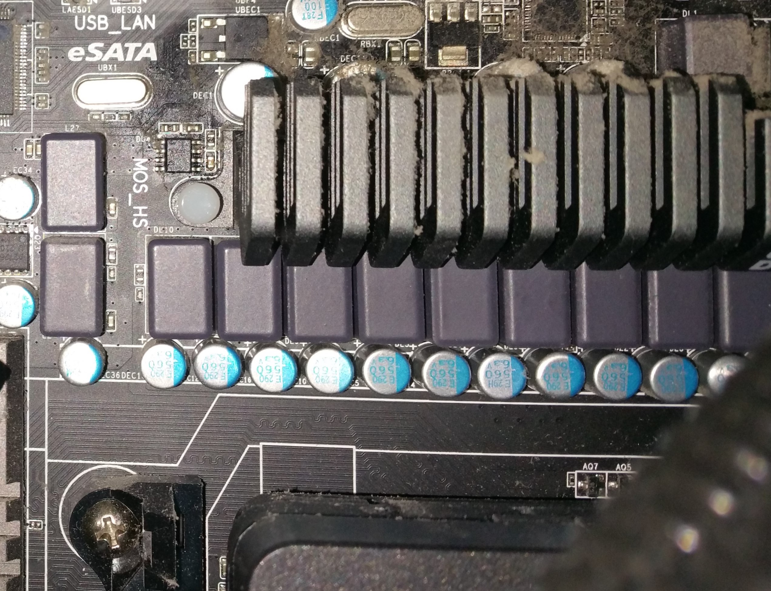
At the time, to match my budget option of an AMD processor that competed with Intel only on the basis of price, I had also bought a fairly budget motherboard. None of those > $150, RGB-equipped, gaming-oriented bells and whistles for me. And thus I had a motherboard with a very crappy VRM (voltage regulator module) solution…have a look for yourself (and pardon the dust):

See those gunmetal-colored blocks just to the right of the miniscule heatsink? Those are the chokes for the VRM, and the components that are behind the heatsink would be the power switching MOSFETs. Generally, there are a few design dimensions for VRM modules - I’m no expert, but here is the 30,000 foot view:
The VRM’s job is to provide a steady voltage (somewhere between 0.8 and 1.5 volts for modern system) to the CPU. When you change your core voltage in the BIOS, the VRMs are what actually effect that setting. Therefore, all of the energy that your CPU dissipates as part of its thermal design power (TDP) rating starts as electrical current flowing through the VRMs. For the low-side voltage (say, 1.3 volts on the FX-8350) and a TDP of 125 Watts, we would see current of ~96 Amperes. That’s quite a lot, which is why VRMs are designed with multiple phases, and sometimes with parallel components within each phase. Obviously, the quality of the components also matters, but I’m not focusing on that in this article. In essence, the quality of the VRM solution on a motherboard determines what processor you can run (how many cores?) and how fast you can run it (what voltage and frequency?).
So, the VRM solution on my motherboard wasn’t great, and the CPU I had already required a lot of power. To boot, I couldn’t help myself from trying to overclock the thing by at least a few hundred megahertz. Finally, I was using an aftermarket cooling solution that did not push any air down onto the board, which meant there was very little airflow for the VRMs. And thus the stability issues began - even at stock speeds, I started having random shutdowns that corresponded suspiciously to high VRM surface temperatures when I checked with an infrared thermometer…or just put my fingers against the heatsink. Ow!
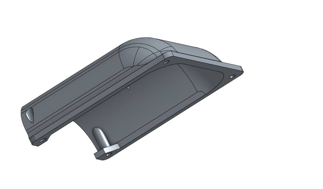
At the time, I decided on the cheapest solution I could. In college, I had access to tech dumps scattered around campus, and had frequently dissected old Dell Dimension and Precision towers. Many of these machines had interesting ducts that forced air directly from a rear case fan over the CPU heatsink. Taking Dell’s (likely inexpensive) solution as inspiration, I CADed up a design in Onshape and printed it out.
Here’s the render:
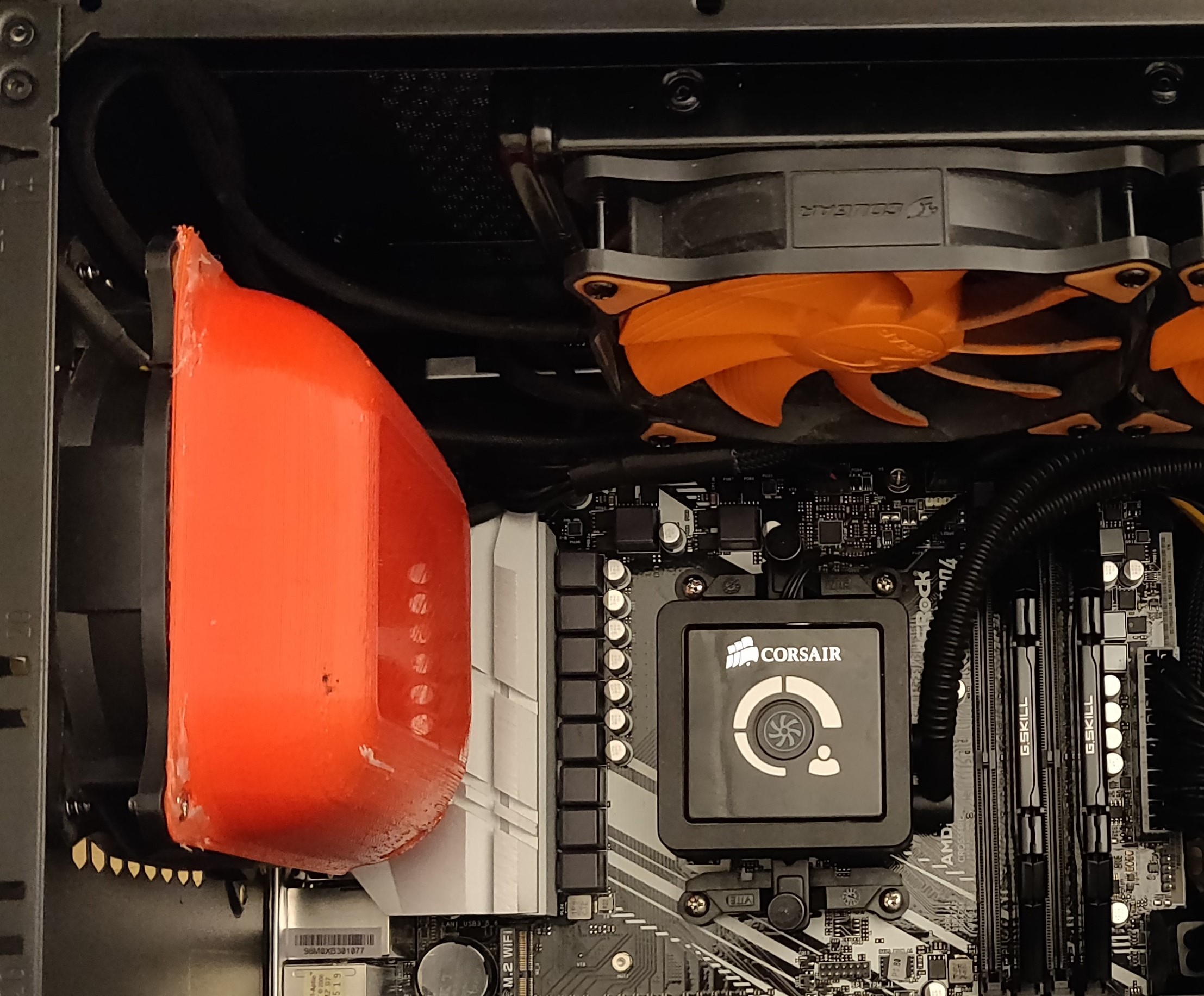
And here’s the final result:

It didn’t come out perfectly, but did exactly what it needed to. After putting this duct in, I saw much reduced VRM temperatures and an improvement in stability to match. The motherboard died a few years later, but I still use this duct and others like it in newer builds. It’s never a bad idea to have better VRM cooling, and this is a really easy way to have the chassis fan do more useful work. Even the theoretically higher-end motherboard I purchased for a Ryzen build has a ridiculous cooling solution that benefits from directed airflow.
If you’re intersted in printing one of these yourself, feel free to contact me for the STL file.
